Core structure of Pump/trigger Cap Unscrambler and Feeder/Pump/Trigger Head Cap Aligner (mainstream centrifugal type):
• Rack/support: Machine base, protective cover
• Power system: Motor + frequency conversion speed regulation, driving the turntable to rotate
• Cover rotating disc (core)
Includes cover slot/workstation plate with slot width compatible with pump cap suction tube, narrower than the cover body
Utilize centrifugal force + gravity to automatically orient and position the pump cover into the designated slot
• Cover separation/guiding mechanism: partition plate, pressing cover plate, ensuring single cover passage and preventing overlapping
• Cap ejection channel: Directed output to the cap screwing machine
• Switching/Exclusion: Automatic return of reverse caps and exclusion of defective caps
Working Principle of Pump/trigger Cap Unscrambler and Feeder/Pump/Trigger Head Cap Aligner (Mainstream Centrifugal Type)
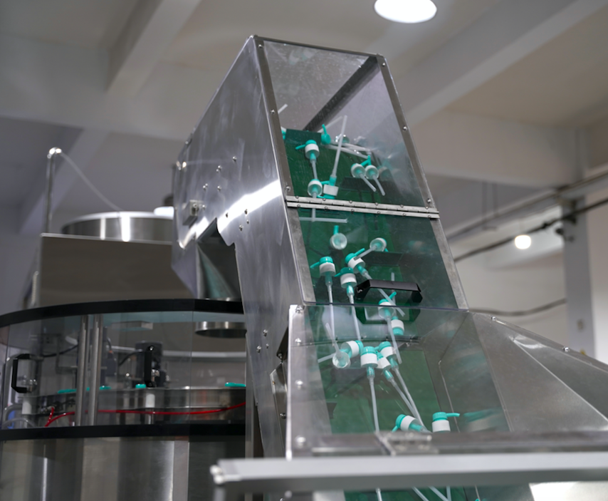
1. Feed: Pour the pump cover into the rotary table area
2. Centrifugal separation: The rotating disk causes the pump cap to disperse under centrifugal force; the center of gravity shifts toward the cap body, automatically flipping it into a standard orientation with the cap body facing upward and the suction tube facing downward within the slot.
3. Directional screening: The slot width is designed to allow only the straw to pass through while the cap remains securely engaged, with the reverse cap being ejected as recycled material.
4. Pump cap removal: Qualified pump caps are discharged along the passage and proceed to the top cover/rotary cap assembly process.
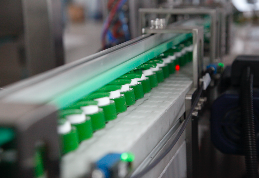
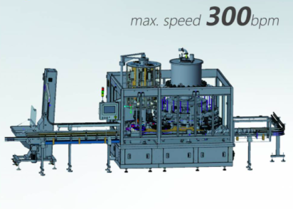
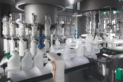
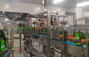
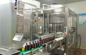
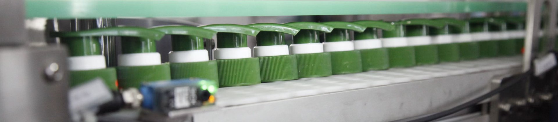
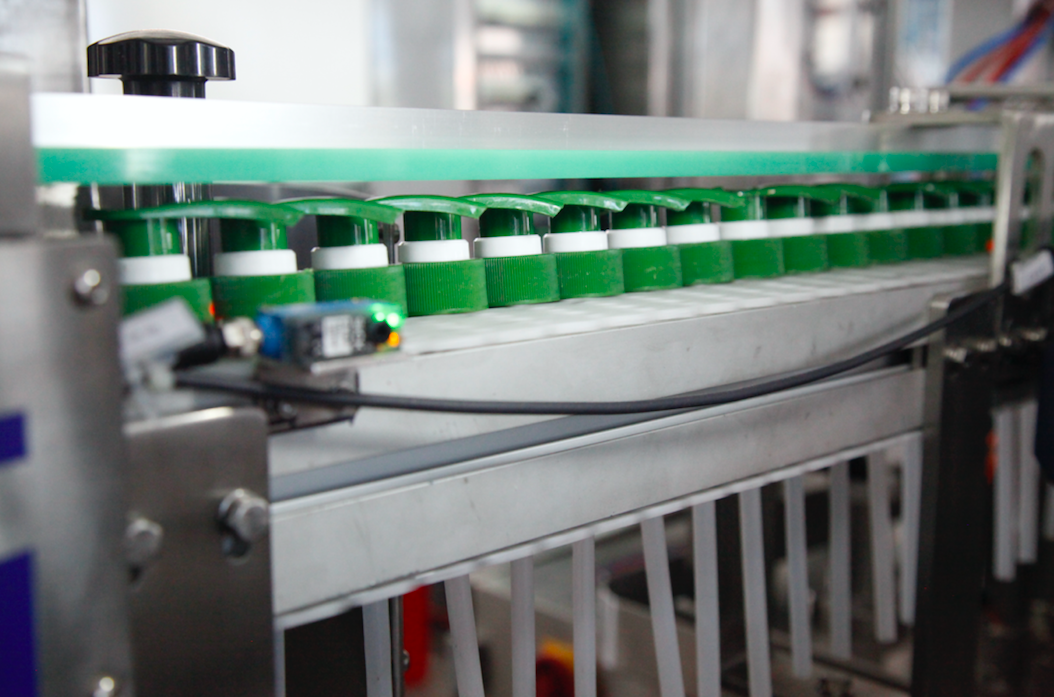
Detailed pictures for this Pump/trigger Cap Unscrambler and Feeder/Pump/Trigger Head Cap Aligner: